
Hardware - Parts, Wiring & Assembly
Bill of materials and build guide for the Flock Noir. See the main README for what the project is and its important experimental disclaimer (this tool is a research aid, not a definitive detector - always visually confirm an actual camera).
Two things that trip everyone up
- The buzzer must be a passive piezo. Active buzzers have a built-in oscillator and play only one fixed pitch - they cannot play the RTTTL tunes. Get a passive one.
- The IR-cut filter is the gatekeeper. A stock camera lens blocks most 850 nm light, so IR detection range is short and finicky. An IR-filter-removed lens dramatically improves it (see optional parts).
Bill of materials
Complete XIAO ALPR reference build
| Part | Qty | Requirement / purpose |
|---|---|---|
| Seeed Studio XIAO ESP32-S3 Sense, Sense expansion board and antenna | 1 | 8 MB flash, PSRAM, camera connector, onboard microSD slot; Seeed hardware guide. |
| Compatible OV2640 camera without IR-cut filter | 1 | Your existing OV2640 is the reference camera. Check the actual camera fitted to your board; do not assume every Sense shipment includes OV2640. |
| 3.3 V-compatible OPT101 analog breakout | 1 | Required for the high-speed optical path. Integrated photodiode and amplifier; TI specification. No separate BPW34 / op-amp needed. |
| ATGM336H NMEA GPS module and antenna | 1 | Keep the existing working setup: TX→D7, optional RX→D6, 9600 baud. Needed for geotagging and WiGLE logging. |
| FAT32 microSD, 4–32 GB | 1 | Required for persistent ALPR, radio and WiGLE logs; also stores recordings. |
| Small passive piezo buzzer | 1 | For distinct tones and Pig Detector siren. Active buzzers cannot play the melodies. |
| ~100 Ω series resistor | 1 | Between D0 and the small passive piezo. A high-current speaker needs a driver; do not drive it directly. |
| 0.1 µF supply bypass capacitor | 1 if absent on module | Close to OPT101 VCC/GND; a breakout may already include it. |
| Short hookup wires / solder, USB data cable, stable USB supply or power bank | As needed | Shared ground, reliable power and USB flashing. |
Pig Detector minimum: XIAO, antenna and passive buzzer; the Sense expansion, camera and OPT101 are not detection inputs in that mode. Add SD for event logs. Wardrive: XIAO, antenna, GPS and SD. The S3 surveys BLE, not Bluetooth Classic. The full ALPR build uses every part above.
Optional / recommended
A rigid enclosure that keeps the OPT101 and camera aimed together, optical shade to prevent saturation, and a suitable near-IR filter can improve measurements. OPT101 responds to visible light as well as near-IR; a filter does not identify an ALPR. Battery options must match Seeed's documented voltage and polarity. A separate, verified 10 Hz / 20 ms IR LED test source is useful for bench testing; a TV remote only checks light sensitivity.
Pin map
Everything below is fixed by the Sense board except the GPS, OPT101 and buzzer, which use free header pins. None of these overlap, so the camera + SD keep working.
| Signal | GPIO | Header pad | Owner |
|---|---|---|---|
| Camera OV2640 (14 pins) | 10,11,12,13,14,15,16,17,18,38,39,40,47,48 | ribbon | Sense board (fixed) |
| microSD - CS | 21 | - | Sense board (SD.begin(21)) |
| microSD - SCK / MISO / MOSI | 7 / 8 / 9 | D8 / D9 / D10 | Sense board (default SPI) |
| PDM microphone (recording) | 42 (clk) / 41 (data) | - | Sense board (fixed) |
| GPS RX (<- module TX) | 44 | D7 | config.h |
| GPS TX (-> module RX) | 43 | D6 | config.h |
| Buzzer signal | 1 | D0 | config.h |
| OPT101 OUT | 2 | D1 | ADC1, works alongside WiFi |
| Free header pins | 3,4,5,6 | D2-D5 | Check boot-strapping before attaching loads |
Wiring
GPS (NMEA GNSS over UART)
GPS module            XIAO ESP32-S3 Sense
-----------           -------------------
  TX      ----------->  D7  (GPIO44)   [ESP RX]
  RX      -----------  D6  (GPIO43)   [ESP TX]
  VCC     ----------->  3V3
  GND     ----------->  GND
If your module uses different pads, just change GPS_RX_PIN / GPS_TX_PIN / GPS_BAUD in
config.h.
Buzzer (passive piezo, 2-pin)
buzzer leg 1 (+)  ------->  D0  (GPIO1)     (optional ~100 ohm in series to soften volume)
buzzer leg 2 (-)  ------->  GND
Passive piezos aren't polarized - if the legs are equal length, either orientation is fine. On power-up the board plays a boot jingle, which confirms the buzzer works.
Assembly
- Attach the antenna to the XIAO's IPEX connector and seat the camera ribbon.
- Format the microSD as FAT32 and insert it into the Sense board's slot.
- Solder the GPS (4 wires: TX->D7, RX->D6, 3V3, GND).
- Solder the buzzer (signal->D0, other leg->GND).
- Fit the IR-cut-free OV2640. Wire OPT101 VCC→3V3, GND→GND, OUT→D1/GPIO2. Use the labeled terminals, not an assumed terminal order.
- Flash the firmware - prebuilt image or from source, see the README install section.
- Power on, join Flock Noir / flocknoir, open
http://192.168.4.1, select ALPR, then enable OPT101 after checking the wiring.
First-light test (no camera target needed)
- Buzzer: hear the boot jingle? Passive buzzer wired correctly. In Settings -> Test, a tune that changes pitch confirms it's passive.
- SD: the UI's microSD tile should read ready.
- GPS: take it outside; the GPS Fix tile flips to FIX once it sees satellites (cold start can take a few minutes).
- IR pipeline: point a TV/AC remote at the lens and press buttons - remotes pulse IR (at a different rate), a quick way to check light sensitivity. This does not validate ALPR timing or the detector. Use the bench checks below.
OPT101 photodiode module (current reference build)
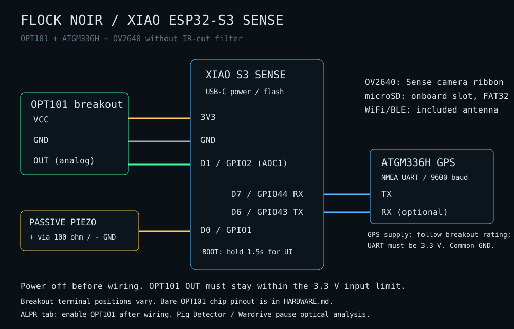
Disconnect USB and battery power before connecting wires. This build uses an OPT101 analog breakout and an OV2640 with its IR-cut filter removed. OPT101 already contains the photodiode and amplifier; no BPW34 or MCP6002 is required. It responds to visible and near-IR light, not exclusively 850 nm.
| OPT101 breakout terminal | XIAO ESP32-S3 Sense |
|---|---|
| VCC / VS / V+ | 3V3 |
| GND | GND |
| OUT / VOUT / analog output | D1 / GPIO2 (ADC1_CH1) |
Terminal order varies by breakout. Confirm labels and its supply requirements; this connection is for a breakout that operates from 3.3 V. A board marked for 5 V only needs its circuit checked before use. Do not put a 5 V output into the XIAO ADC. Start with short wires; put supply decoupling at the sensor if the breakout does not include it. TI recommends 0.01-0.1 uF supply bypassing.
Bare OPT101 chip, standard single-supply circuit
These are IC pin numbers viewed from above, not breakout terminal positions. Use the package's pin-1 marker and the TI datasheet.
| IC pin | Connection |
|---|---|
| 1, VS | 3V3 |
| 3, -V | GND |
| 8, Common | GND |
| 4, feedback | Join to pin 5 to use the internal 1 Mohm resistor |
| 5, output | D1 / GPIO2 |
| 2, negative input | Leave unconnected in this standard circuit |
| 6 and 7 | No connection |
Bring-up
- Power on and connect to Flock Noir, password flocknoir. Open
192.168.4.1. - Select ALPR, then enable IR photodiode sensor. Watch the raw count and waveform as you cover/uncover the OPT101. The firmware cannot prove a sensor is connected simply by reading an ADC baseline.
- Check for headroom in actual outdoor lighting. OPT101 is not rail-to-rail; its amplifier may saturate well below the ADC maximum. Lower incoming light or use an appropriate optical filter if the waveform flattens under bright light.
- A TV remote is useful for checking response, but is not a valid ALPR test source. Verify a known 10 Hz, 20 ms light pulse and reject other frequencies.
- In ALPR mode, verify ~1 kHz OPT101 sampling, camera analysis fps, WiFi/BLE readiness and drop/gap diagnostics while logging. Switch to Pig Detector or Wardrive and confirm optical sampling pauses; these modes are exclusive. See detection and radio validation.
The supplied camera defaults now use lower fixed exposure/gain (150 / 2) for an IR-cut-free OV2640. Tune those under real lighting. Point the camera and OPT101 at the same area to make cross-sensor evidence more useful. A suitable 850 nm bandpass filter can reduce visible-light interference; verify the actual filter transmission specification. No optics can establish camera identity.
GPIO conflicts to avoid
The OUI Spy reference board is not the Sense peripheral layout. Keep the passive buzzer on D0/GPIO1. GPIO21 is microSD CS, not an available NeoPixel pin. GPS stays on D7/GPIO44 RX and D6/GPIO43 TX. For your ATGM336H, the firmware uses the external UART profile at 9600 baud. Keep its existing power wiring if working; bare GNSS modules and breakouts can have different supply ratings.
Raspberry Pi wiring (the pi/ target)
The Raspberry Pi build uses the same sensors on the Pi's 40-pin header:
| Signal | Pi header pin | BCM |
|---|---|---|
| Buzzer (+) | 12 | GPIO18 (PWM) |
| Buzzer (-) | 6 | GND |
| GPS TX -> Pi | 10 | GPIO15 RXD |
| GPS RX <- Pi | 8 | GPIO14 TXD |
| MCP3008 CLK / DOUT / DIN / CS | 23 / 21 / 19 / 24 | GPIO11 / 9 / 10 / 8 (SPI0) |
| IR receiver front-end out | MCP3008 CH0 (CH1, CH2 for more) | - |
The Pi has no analog input, so the IR photodiode front ends above feed an MCP3008 ADC on SPI. The full pin-by-pin guide, header diagram, and placement notes are in pi/README.md.